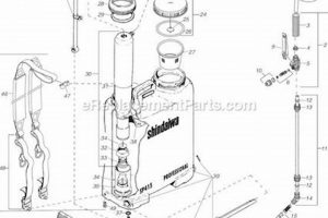
A visual representation detailing the components of a portable spraying device, specifically those manufactured by H.D. Hudson Manufacturing, illustrates the arrangement and identification of its constituent pieces. This schematic typically encompasses elements such as the tank, pump assembly, wand, nozzle, and various seals, gaskets, and connectors, providing a comprehensive overview of the sprayer’s construction. For example, a diagram would show how the pump connects to the tank and how the hose attaches to the wand, highlighting the relationship between these parts.
Access to such a resource offers several advantages, including facilitating repair and maintenance procedures by enabling users to accurately identify and replace worn or damaged components. Furthermore, these diagrams aid in understanding the operational mechanics of the sprayer, promoting efficient usage and troubleshooting. Historically, these diagrams were primarily available in printed manuals; however, digital versions are increasingly common, offering enhanced accessibility and searchability.
The subsequent sections will delve into specific components typically featured in these diagrams, examine common issues that necessitate parts replacement, and explore resources for obtaining both diagrams and the necessary parts for maintenance and repair.
Tips Regarding Bak Pak Backpack Sprayer Hudson Sprayer Parts Diagram Utilization
The following guidance aims to optimize the usage of component schematics for portable spraying devices manufactured by H.D. Hudson Manufacturing, ensuring effective maintenance and repair.
Tip 1: Always consult the component schematic prior to disassembly. This action minimizes the risk of damaging parts during the disassembly process.
Tip 2: Verify the part number against the diagram before ordering replacements. Matching the correct part number ensures compatibility and avoids unnecessary returns.
Tip 3: Utilize exploded views to understand the order of assembly. Assembling components in the correct sequence is critical for proper functionality and preventing leaks.
Tip 4: Note the location of all seals and gaskets as indicated on the diagram. Proper placement of seals and gaskets is essential for maintaining pressure and preventing fluid loss.
Tip 5: When disassembling, document the position of each part relative to others, even if the diagram seems straightforward. This documentation aids in reassembly, especially if the project is interrupted.
Tip 6: Compare the physical part with its representation in the diagram to confirm identification. This visual confirmation helps to prevent misidentification, especially with similar-looking parts.
Tip 7: Keep a clean workspace and organize disassembled parts logically, referring to the diagram as a guide. Organized disassembly minimizes the risk of losing parts and simplifies the reassembly process.
Adhering to these guidelines will enhance the efficiency and accuracy of repairs and maintenance procedures. Correctly interpreting the schematic leads to a more reliable and longer-lasting spraying device.
The following sections will explore specific components typically featured in these schematics, common issues that necessitate parts replacement, and resources for obtaining both the diagrams and the necessary parts for maintenance and repair.
1. Identification accuracy
In the context of portable spraying devices, precision in identifying components is paramount for effective maintenance and repair, and relies heavily on the use of a component schematic.
- Part Number Correlation
The parts diagram provides definitive part numbers. Accurate identification through the diagram ensures the correct replacement is ordered, preventing delays and operational inefficiencies. Misidentification stemming from reliance on visual similarity alone can lead to incompatibility and further damage to the sprayer.
- Assembly Order Comprehension
The component schematic illustrates the correct sequence for assembling components. Accurate identification of part placement, guided by the diagram, is critical for ensuring proper function and preventing leaks. Incorrect assembly, even with the correct parts, can compromise the sprayer’s operation.
- Seal and Gasket Placement
Diagrams precisely indicate the location and orientation of seals and gaskets. Correct identification of these components’ placement ensures a leak-proof seal, essential for maintaining pressure within the spraying system. Errors in seal placement, arising from misinterpreting the diagram, can lead to pressure loss and decreased efficiency.
- Component Differentiation
Spraying devices often contain components that appear similar but possess distinct functions and specifications. The parts diagram provides the necessary detail to differentiate these components accurately. For example, two nozzles might have similar shapes but different spray patterns; accurate identification ensures the correct pattern is applied for the intended task.
The reliance on accurate component identification, facilitated by a comprehensive schematic, directly influences the longevity and performance of portable spraying devices. Without this precision, maintenance becomes guesswork, potentially leading to further damage and increased operational costs. Therefore, the parts diagram serves as an indispensable tool for users seeking to maintain and repair these devices effectively.
2. Component location
The precise location of each component within a portable spraying device, especially Hudson models, is visually represented in the relevant parts diagram. The diagram functions as a map, explicitly defining the spatial relationship between each part, crucial for both assembly and disassembly. A misidentification of a component’s location directly translates to potential errors during repair, possibly leading to incorrect reassembly or damage to surrounding parts. For instance, the diagram clarifies the placement of the check valve within the pump assembly, preventing its reversal which would render the sprayer inoperable. Thus, understanding the component location, as revealed by the diagram, is indispensable for maintaining the functional integrity of the spraying device.
Furthermore, knowledge of component location, as derived from the parts diagram, facilitates efficient troubleshooting. By referencing the diagram, a user can quickly identify and access a suspected faulty component. For example, if the sprayer exhibits a loss of pressure, the diagram can guide the user directly to the location of seals, o-rings, and the pressure regulator, common culprits behind such issues. Without a precise understanding of component location, the troubleshooting process becomes significantly prolonged and less effective, potentially requiring extensive disassembly and reassembly of functional parts.
In summary, the parts diagram provides essential locational information for all components. Correct identification and component placement ensures appropriate ordering and placement, which ensures the effectiveness and efficiency of the portable sprayer. Without precise identification, issues during troubleshooting may arise resulting in extended repair periods and potential unintentional damage. Thus, accessing and understanding the components of the parts diagram can be essential for effective use and maintenance.
3. Assembly order
The proper sequencing of component installation is critical to the functionality and longevity of portable spraying devices. A component schematic serves as a blueprint, defining the precise order in which parts must be assembled. Deviations from this prescribed order can result in operational failures or damage to the device.
- Sequential Integrity
The parts diagram dictates the order of assembly, ensuring that components are installed in a manner that supports the overall structure and operation. For example, the diagram might specify that the pump cylinder must be installed before the piston to prevent damage to the piston rings. Incorrect sequencing compromises the integrity of the assembly.
- Interlocking Mechanisms
Portable sprayers often employ interlocking mechanisms that depend on specific assembly order. The diagram clarifies how these mechanisms function and the sequence required for their proper engagement. Failing to adhere to this order can result in misalignment, preventing the mechanism from functioning correctly. For instance, the diagram may show a specific clip that secures the spray wand to the handle, and it must be assembled before the handle is fully attached to ensure proper retention.
- Seal and Gasket Compression
The component schematic illustrates how the compression of seals and gaskets is achieved through the proper assembly sequence. Correct sequencing ensures that these components are properly compressed, creating a leak-proof seal. Incorrect assembly can lead to insufficient compression, resulting in leaks and pressure loss. For instance, the diagram may show that the nozzle body must be tightened to a specific torque value after the O-ring is in place, to ensure a proper seal and prevent leaks.
- Prevention of Component Stress
The diagram guides the user in assembling components in a manner that minimizes stress on individual parts. Proper sequencing can prevent undue strain on delicate components, extending their lifespan. Incorrect assembly can introduce stress points that lead to premature failure. An example is a section that has several connections on the hose. Putting these connections together in the wrong order puts unnecessary strain on the hose, leading to cracks and leaking.
A parts diagram is essential for maintaining correct sequencing when working with spray devices. The consequences of failing to adhere to the designated assembly sequence range from minor leaks to complete operational failure. The schematic provides a comprehensive guide to the proper order and function of each part, which is critical to the life and effectiveness of the sprayer.
4. Seal placement
Proper seal placement is crucial for maintaining the functionality and efficiency of portable spraying devices. Component schematics are essential tools for ensuring accurate seal installation during assembly or repair.
- Preventing Leaks
The primary function of seals within a sprayer is to prevent leaks. Component schematics delineate the precise location of each seal, ensuring its correct positioning to maintain pressure and prevent fluid loss. For example, a diagram will indicate the position of the o-ring between the pump cylinder and the tank, preventing leaks that would reduce spraying effectiveness.
- Maintaining Pressure
Spray devices rely on consistent pressure for optimal performance. Seals must be correctly positioned to prevent pressure loss. The schematic provides detailed illustrations of seal locations, enabling users to maintain the device’s pressure. The parts diagram of the Hudson sprayer will show exactly where the pressure relief valve seal goes to prevent overpressurization.
- Protecting Components
Seals protect internal components from damage caused by leaks or exposure to chemicals. The component schematic guides users in positioning seals to protect sensitive parts, enhancing the device’s lifespan. An example would be the positioning of a seal to prevent chemical exposure to the pump mechanism.
- Ensuring Compatibility
Component schematics often specify the type of seal required for each location. Proper seal placement, guided by the schematic, ensures compatibility with the chemicals being sprayed, preventing degradation or failure. The diagram should differentiate materials to avoid chemical interactions with the device components.
Correct seal placement is integral to the effective operation and maintenance of portable sprayers. A parts diagram of the Hudson sprayer serves as an essential reference for ensuring accurate seal installation, preventing leaks, maintaining pressure, protecting components, and ensuring compatibility with sprayed chemicals.
5. Troubleshooting assistance
Component schematics for portable spraying devices, such as those produced by H.D. Hudson Manufacturing, provide critical troubleshooting assistance. The parts diagram functions as a visual aid, enabling users to identify the location and arrangement of individual components. This facilitates the diagnosis of malfunctions by correlating symptoms with specific parts, thereby streamlining the repair process. For instance, if a sprayer exhibits a loss of pressure, the parts diagram assists in identifying the location of seals, valves, and the pump assembly, allowing the user to inspect these areas for damage or wear. The presence of the diagram inherently reduces diagnostic time and minimizes the potential for misidentification of the root cause of the problem.
The effectiveness of this assistance is predicated on the diagram’s accuracy and the user’s understanding of its symbology. Clear diagrams with labeled parts enable quick identification of potential failure points. When a sprayer fails to prime, for example, the parts diagram guides the user to examine the check valve, its spring, and associated seals. The diagram allows the user to disassemble the pump assembly systematically, without unnecessarily removing other components, saving both time and effort. Furthermore, by visually confirming the arrangement and condition of the parts against the diagram, potential assembly errors can be identified and rectified. The schematics may also indicate torque specifications for certain fasteners, ensuring proper reassembly to prevent future issues.
In conclusion, the integration of a component schematic directly enhances the troubleshooting capabilities associated with portable spraying devices. By providing a visual reference for parts identification, arrangement, and potential failure points, the parts diagram streamlines the diagnostic process, minimizes downtime, and promotes effective maintenance. The availability of accurate and easily accessible parts diagrams thus represents a significant benefit for users seeking to maintain and repair their equipment.
6. Maintenance guide
A maintenance guide serves as an instructional resource providing detailed procedures for the upkeep and repair of equipment. When paired with a component schematic, such as a parts diagram, it enhances the user’s ability to perform effective maintenance on items such as portable spraying devices manufactured by H.D. Hudson Manufacturing.
- Parts Identification for Service
Maintenance guides often reference components by name or number. Parts diagrams provide a visual representation, enabling users to accurately identify the parts described in the maintenance guide, particularly when disassembling or reassembling complex mechanisms. Without the visual aid of the diagram, correct parts identification becomes substantially more challenging.
- Disassembly/Reassembly Sequencing
Maintenance guides typically outline the necessary steps for disassembly and reassembly. Parts diagrams clarify the spatial relationships between components, assisting the user in understanding the correct sequence and orientation during these processes. Errors in sequencing can lead to damage or improper functioning of the device.
- Torque Specifications and Fastener Details
Maintenance guides may specify torque values for fasteners and other critical assembly details. Parts diagrams help users identify the specific fasteners being referenced, ensuring that the correct tightening procedures are applied. Inadequate or excessive torque can compromise the integrity of the assembly.
- Troubleshooting Diagnostics
Maintenance guides often include troubleshooting sections identifying potential issues and their likely causes. Parts diagrams aid in locating and inspecting the components associated with these issues, streamlining the diagnostic process. Visual confirmation of part condition, as depicted in the diagram, can accelerate problem resolution.
The synergy between a maintenance guide and a component schematic significantly improves the efficacy of maintenance procedures. By integrating textual instructions with visual representations, the user gains a more complete understanding of the equipment, resulting in more accurate and efficient maintenance. Such integration is particularly beneficial for complex devices where parts identification, sequencing, and specific technical data are critical for successful maintenance and repair.
7. Parts replacement
The necessity for parts replacement in portable spraying devices, particularly bak pak backpack sprayers from H.D. Hudson Manufacturing, is intrinsically linked to the availability and utilization of accurate component schematics. The efficient and correct substitution of worn or damaged components relies heavily on the detail provided within a parts diagram.
- Accurate Part Identification
The component schematic provides the definitive source for part numbers and visual representation. Precise identification of the correct replacement part prevents ordering errors and ensures compatibility. For example, identifying the correct nozzle type using the diagram avoids misapplication of chemicals due to incorrect spray patterns.
- Proper Disassembly and Reassembly
The parts diagram illustrates the sequence of component assembly and disassembly. Understanding the order is crucial for replacing a part without causing damage to surrounding elements. Removing a worn pump seal, for instance, requires disassembling the pump in a specific sequence outlined in the diagram to avoid component breakage.
- Seal and Gasket Integrity
Replacement of parts often necessitates the replacement of associated seals and gaskets. The component schematic indicates the location and type of these sealing elements. Failure to replace seals and gaskets concurrently with the main component, or using incorrect replacements as detailed in the diagram, can result in leaks and reduced device efficiency.
- Ensuring System Compatibility
Certain parts are designed to function specifically within a larger system. The component schematic aids in understanding these relationships and ensuring that replacement parts are compatible with the existing system configuration. Installing an incompatible pressure regulator, for example, can lead to over- or under-pressurization, potentially damaging other components.
The correlation between accurate parts replacement and the utilization of a bak pak backpack sprayer H.D. Hudson Manufacturing parts diagram is critical for effective maintenance. Access to and understanding of the component schematic ensures that repairs are conducted efficiently, correctly, and with minimal risk of further damage to the spraying device.
Frequently Asked Questions
The following section addresses common inquiries regarding the use and interpretation of component schematics for portable spraying devices, specifically those manufactured by H.D. Hudson Manufacturing.
Question 1: Why is a component schematic essential for maintaining a portable sprayer?
A component schematic provides a visual representation of all parts, their location, and their relationship to one another. This is critical for accurate part identification, proper assembly, and effective troubleshooting, ensuring the longevity and efficient operation of the sprayer.
Question 2: Where can a reliable parts diagram for a specific Hudson sprayer model be located?
Reliable diagrams are typically found within the original product manual, on the manufacturer’s website, or through authorized parts distributors. Ensuring the diagram corresponds precisely to the sprayer’s model number is essential.
Question 3: How does a component schematic aid in troubleshooting a sprayer malfunction?
The parts diagram allows a user to visually trace the fluid pathway, identify potential leak points, and isolate malfunctioning components. This visual aid significantly reduces the time required to diagnose and repair common issues.
Question 4: What information beyond part location does a typical component schematic provide?
Beyond location, a parts diagram typically includes part numbers, assembly order, and may indicate specific hardware requirements, such as fastener torque specifications. This comprehensive information promotes accurate and safe repair procedures.
Question 5: What precautions should be taken when disassembling a sprayer using a parts diagram as a guide?
It is advisable to photograph each stage of disassembly and to carefully organize removed parts. Furthermore, always consult the diagram to identify potential spring-loaded or pressurized components before disassembly to avoid injury or damage.
Question 6: Is it necessary to replace all seals and gaskets when replacing a primary component?
While not always mandatory, replacing seals and gaskets during component replacement is generally recommended. New seals ensure a proper fit and prevent leaks, maximizing the lifespan and efficiency of the repair.
Understanding and utilizing a component schematic is paramount for effective maintenance and repair of portable spraying devices. Correct interpretation of the diagram translates to increased sprayer lifespan and operational efficiency.
The next section will delve into advanced troubleshooting techniques for portable spraying devices.
Conclusion
The preceding analysis has demonstrated the critical role of the bak pak backpack sprayer hudson sprayer parts diagram in the effective maintenance and repair of portable spraying devices. Precise component identification, accurate assembly order adherence, and facilitated troubleshooting are all directly dependent on the availability and proper interpretation of this visual aid. These diagrams, therefore, transcend their function as mere schematics, becoming indispensable tools for users seeking to maximize the lifespan and operational efficiency of their equipment.
The continued reliance on, and refinement of, these component schematics remains essential. Users are encouraged to seek out and familiarize themselves with the diagrams specific to their equipment models. Doing so will contribute significantly to reducing equipment downtime, minimizing repair costs, and promoting safer and more effective spraying practices in diverse applications.


